Using Modeling to Reduce Backbreak
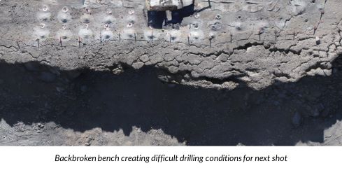
In drilling & blasting operations, backbreak can be a persistent issue that haunts site and production benches, resulting in difficult conditions for subsequent blasts. Backbroken conditions can slow down drill production times, sacrifice hole quality and increase oversize in sequential blasts, not to mention creating safety hazards.
The root cause of backbreak on sites may be due to several factors such as geology, loading, timing, both in conjunction with or solely from poor blast design. This document will address how to use modeling techniques to improve highwalls, specifically by looking at modeling overall blast design, burden analysis, loading, and timing relief. It’ll also explore how we can use modeling conditions before resorting to methods of perimeter control, like pre - splitting, as a solution.
Using the “Rules of Thumb”
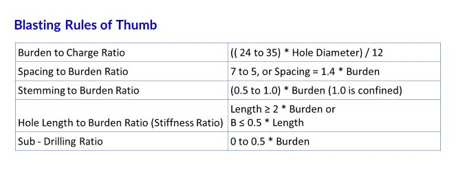
When first designing a blast, the multiple “Rules of Thumb” should come into mind. As blasters, these rules are instinctive when laying out and designing shots. In almost all cases, abiding by these rules can help reduce or eliminate backbreak. Conversely, not using the rules is often a major cause of back break on site. However, there are always cases where the rules of thumb may get overlooked, or slightly bent due to site conditions like difficult or favorable geology.
Adding 3D Modeling Technology
One of the big causes of back break is inadequate burden relief. Adding 3D modeling to the rules of thumb gives blast design an entirely new dimension. 3D modeling the bench and blast design using AI blast design tools allows blasters to easily see and account for important features in the bench such as front row burdens, relief, powder factor, and geology.
Modeling Burdens
They aid blasters in designing better front row burdens allowing for improved relief in subsequent rows of the blast.
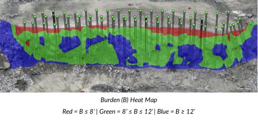
Being able to view areas of inadequate or excessive burden helps blasters design angled drill holes and helps them decide where they can look to open their shot (initiate the blast). If, for example, the model shows a heavy toe, angled holes can be accurately modeled to minimize the risk of flyrock and improve backbreak conditions caused by the poor relief.
Profiling an open face before blasting is not only safer, it also allows blasters to optimize their designs to obtain the best blast results.
Modeling Loading
When loading issues are causing back break the major concerns are relief and powder factor. Loading holes to the proper powder factor is critical to maintain or even improve blast outcomes. This is especially important when loading holes that may be angled, neighboring, or crossing. Being able to carry over the drill design into the blast design or adding deviation measurement data into a 3D model can help blasters see and account for angled, neighboring, and crossing holes in their loading plans.
Another loading issue that causes backbreak comes from excess energy being released into the bench from overloading holes. If not compensated for with proper relief this can have a negative impact on the surrounding geology. The opposite of overloading holes, but just as disasterous for bench maintenance, is underloading holes. This creates a negative effect as insufficient energy can’t move the rock as designed. It merely displaces it enough to make surrounding site conditions dangerous and makes it difficult to resume work.
By using 3D models to better visualize and understand bench information beyond drill holes and front row burdens, like bench geology features can be easily seen and accounted for in the blast loading design.
Modeling Timing
In parallel to loading the blast, timing also plays a crucial role in either improving or serving as a root cause of backbreak. While starting with the rules of thumb as guidelines, incorporating 3D modelling greatly helps blasters in visualizing their blast designs and improving blast outcomes.
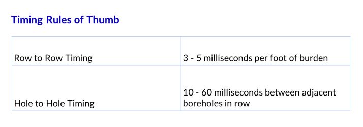
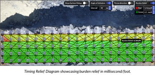
The rules of thumb establish ranges for appropriate hole to hole timing and row to row timing. 3D Modelling allows blasters to see where to refine those numbers, and where to ignore them. For example, there are many geological conditions where these ranges should be adjusted or even stretched. Timing is vital to ensure there is proper relief for the rock to move to reduce any energy redirected back towards resulting highwalls. Properly modeling the timing of the blast, visualizing timing contours, throw direction, and burden relief will help blasters reduce backbreak issues stemming from timing designs.
Why Modeling is Better than Other Backbreak Control Techniques
Following the rules of thumb paired with modeling techniques can help reduce or eliminate backbreak that may be a persistent issue in operations. Leaning on methods of perimeter control such as pre - splitting, smooth wall or buffer blasting, or even trim blasting may be very productive methods in reducing backbreak, but they can come with high drilling costs and also potential high seismograph readings. Incorporating these modeling methods can help blasters design better blasts thereby reducing any backbreak they may be facing without adding additional drilling techniques.
![]()
Check out our 2 Free E-books on AI applications for the drilling, blasting, and mining industries to see all the amazing advances that are available.
AI Guide for Drilling and Blasting
AI Guide for Mining
TLDR? Watch our videos instead:
YouTube
Follow us on:
Facebook
X (Twitter)
LinkedIn