The Ultimate Guide To Quarry Bench Mapping Using Drone Autopilot
Bench Mapping made easy by Strayos
The ever growing popularity of drones has led various industries to incorporate drones into their day to day operations. Effective data collection technique is the key in making commercial drone programs successful in enterprises and integrating into the operational workflow. For example: Drilling & Blasting in Quarry/Mining industry.
Bench mapping using drones can generate accurate 3D geometry of the bench using Strayos platform and operational insights are produced for Drill & Blast design and decission analysis. We recommend using Autopilot mode for drone flights, for the best R.O.I., i.e., Repeatability, Optimization & Improvement for your projects. Getting familiar with new techniques can be a task at times and hence we offer a step by step guide to incorporate the use of autopilot in drone data collection.
Autopilot Flight Path Design
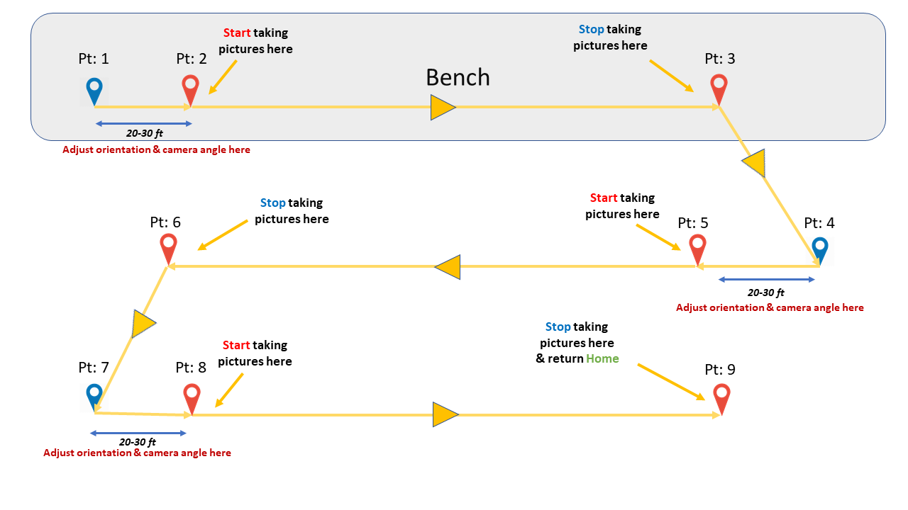
Autopilot Flight Path Design for a Bench using Litchi
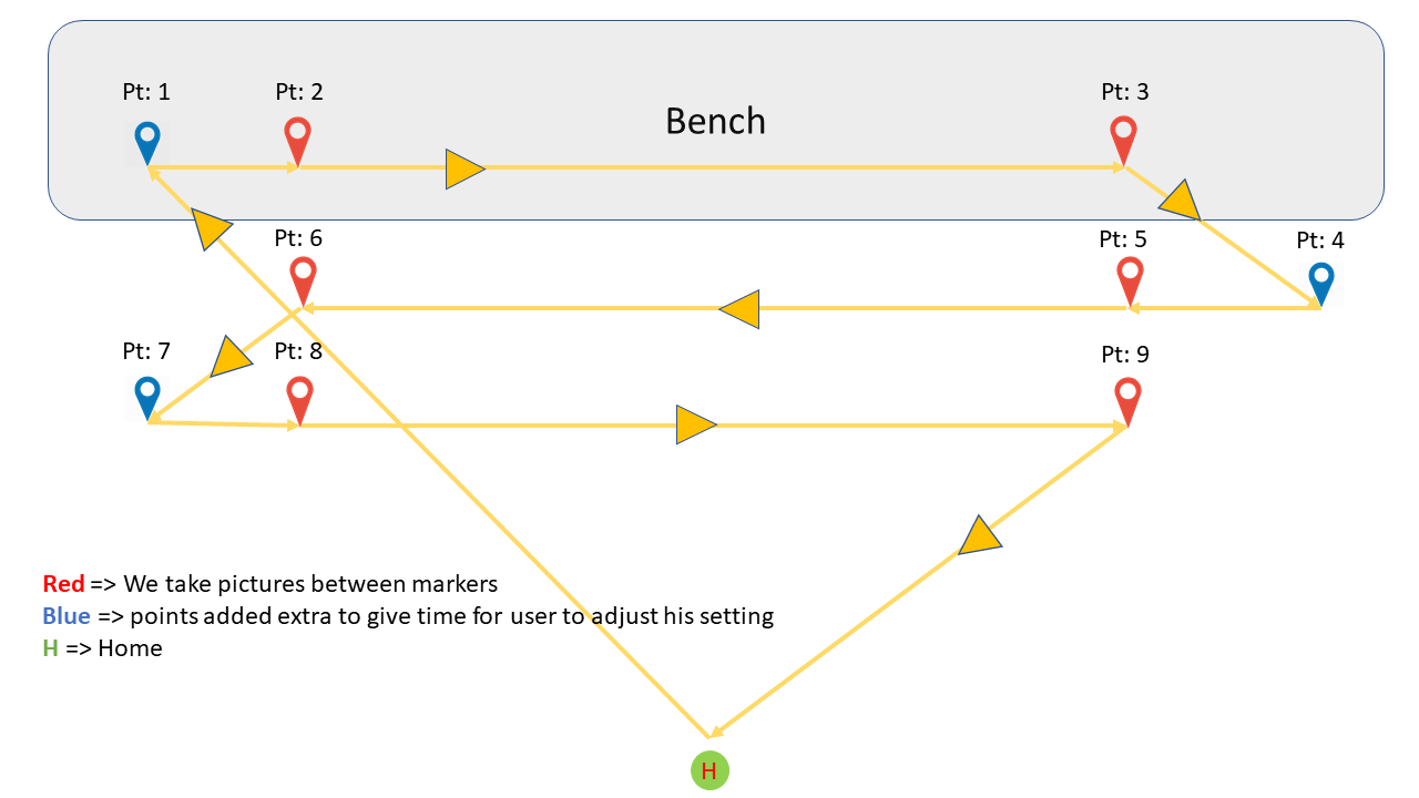
The region between the red markers is the zone we need to map.
The flight path can be designed using three simple steps:
- Gauge the bench heights and flight heights required
- Add waypoints
- Set the mission settings
Step 1:
A. Make a manual flight to gauge the bench measurements and some flight parameters.
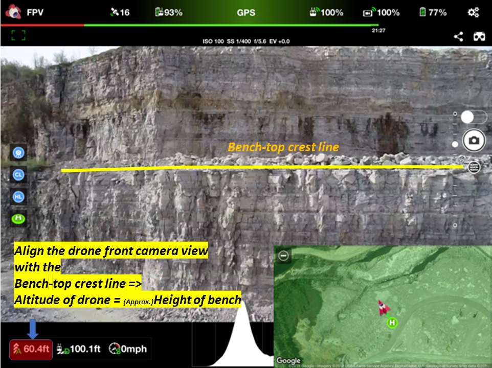
This will help the user determine the bench height.
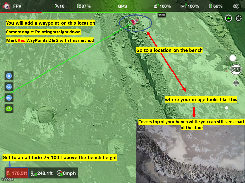
Best Practice: Fly at a height of 75ft to 100ft above the bench height
B. Deciding where to add waypoints for first pass: Make sure your image satifies the following criteria in the Front Person View (FPV) mode as you fly to a location to start marking up waypoints ->
Top of the bench: Locate the Red Waypoints 2 & 3 as shown in Flight Design above. Fly to one end of the zone to be mapped:
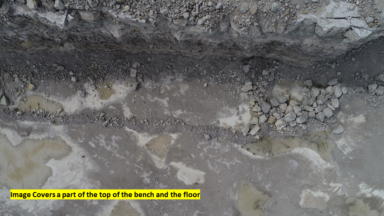
Floor of the bench: Locate Red Waypoints 5 and 6 as shown in Flight Design. Ensure that your image characteristics resemble the following in FPV mode:
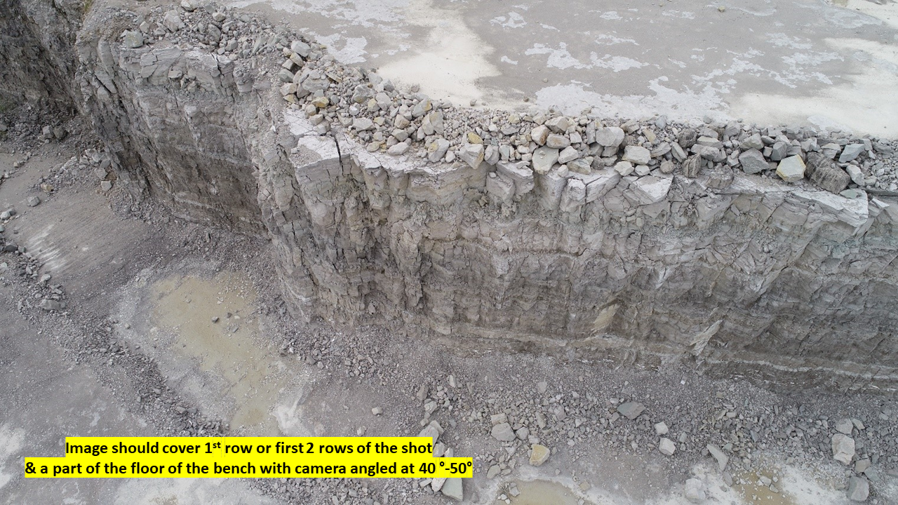
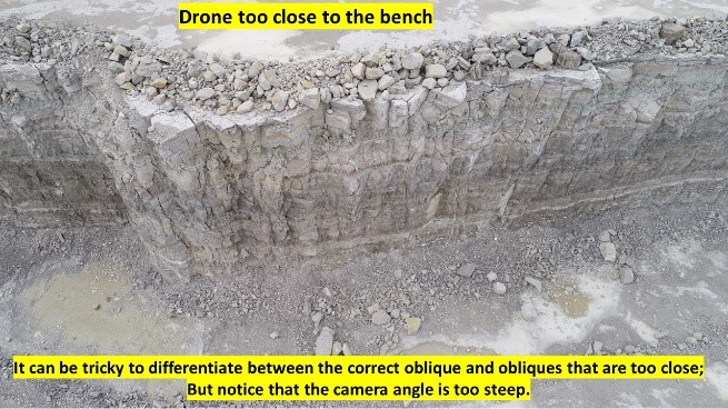
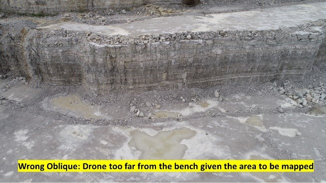
Obliques: Adjust the distance of the drone from the bench and set the camera angle around 40° - 50° to mark Red Waypoints 8 and 9 as shown in Flight Design. Your image characteristics should resemble the following:
Step 2:
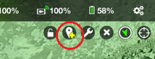
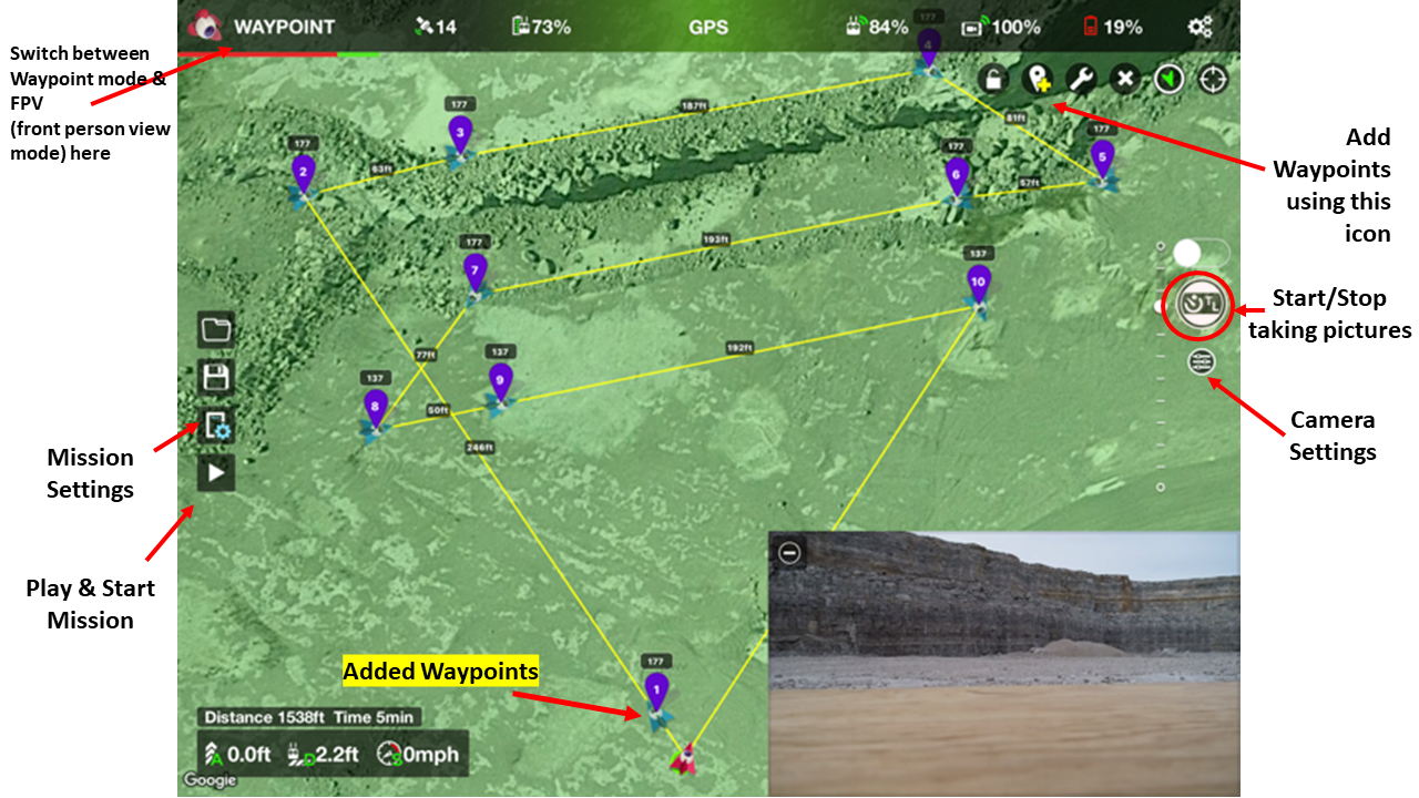
Once the locations for RED waypoints are estimated, add waypoints to those locations using waypoint icon on the top right corner of the screen and set the required altitude or flight heights by tapping on the waypoints to open waypoint settings
Add the Blue waypoints as shown in the map design above. These additional blue points are added to give the pilot some time to adjust the drone orientation/rotation and camera angle as per the type of pass the drone is making, i.e., Top down or Oblique, before it reaches the mapping zone.
Step 3:
Set the cruising speed of the drone, maximum flight heights and other parameters from 'Mission settings'. Set Time interval for clicking pictures under 'Camera settings'. Hit 'Play' to upload mission and fly!
Setting time interval for clicking pictures helps the pilot decide overlap. This is a very important step. To set overlap
Choose Camera Settings > Photo Settings > Capture Mode > Interval > "time in seconds"
Best Practices:
Interval = 2s or 3s
Cruising Speed = 5 mph - 7 mph
gives a good overlap of 70% - 80%
The R.O.I
- Repeatability: the flight missions can be saved and reused for new projects by just changing some parameters like flight heights and drone cruising speed
- Optimization: this process optimizes the flight time and flight control thus increasing the efficiency of the process
- Improvement: improved accuracy due to consistency of the data collected and improved processing times since no redundant images are collected
![]()
Check out our 2 Free E-books on AI applications for the drilling, blasting, and mining industries to see all the amazing advances that are available.
AI Guide for Drilling and Blasting
AI Guide for Mining
TLDR? Watch our videos instead:
YouTube